SEM photos of hollow fiber membrane for UF
Ultrafiltration
- High fouling resistance and oxidation resistance
- Effective recovery capability of cleaning flux
- Large flux
- Good separation performance
- First class mechanical strength
- Outstanding hydrophilicity
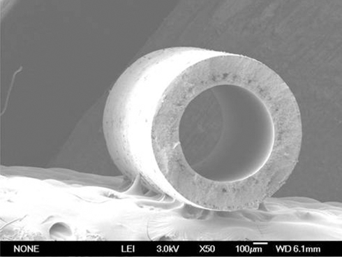
Cross section
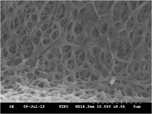
Internal surface
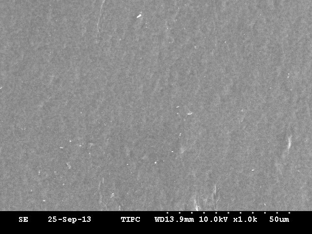
Surface
High performance comes from typicial anisotropic membrane microstructure.
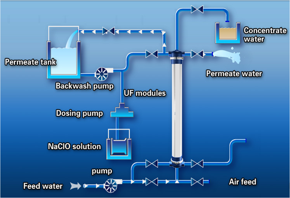
schematic diagram of UF process
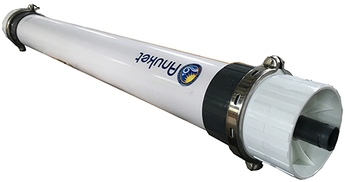
Specification and basic parameters of Anuket UF Membrane Module
|
Basic parameters |
|
|
Model |
AK-70/2000 |
| Type of membrane structure | Hollow fiber membrane |
| Membrane material | PVDF |
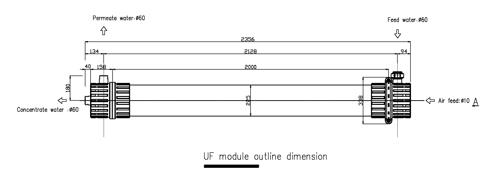
| Dimensions(mm) | Ф225×2358 |
| Diameter of connecting pipe (mm) (Coupling) | Ф60 |
| Area of membrane (m2) | 70 |
| Pore Size (μm) | 0.05 |
| Diameter of fiber outside/inside (mm) | 1.3/0.7 |
| Average flux of purified water ①( L/m2·h) | 300 |
| Material of casing | ABS/UPVC/PMMA |
| Head adhesive | Epoxy resin |
| Weight of modules (kg) dry/wet | 60/100 |
| Capability | |
| Permeate water production ② (t/h) | 2.5~4.5 |
| Turbidity of permeate water ③ (NTU) | ≤0.1 |
| Permeate water sludge density Index | ≤2 |
| Permeate water TSS | <1 |
| Removal rate of virus | ≥99% |
①Under the conditions of 25℃, 0.10MPa.
②The feed water is raw water.
③The turbidity of feed water is less than 50 NTU.
| Typical process conditions of membrane modules | ||
| Recommended operating conditions | Raw water source | Tap water, groundwater, surface water, sea water or urban reclaimed water |
| Designed flux (L/m2·h) | 45~120
(Selected according to the water pretreatment) |
|
| Maximum inlet water turbidity (NTU) | 200 | |
| Maximum inlet water particle diameter (μm) | ≤100 | |
| PH range | 2~11 | |
| Temperature (℃) | 5~40 | |
| Maximum inlet pressure (MPa) | 0.3 | |
| Maximum trans- membrane pressure (MPa) | 0.05~0.15 | |
| Oil content (mg/L) | < 0.2 | |
| Backwashing | Backwashing period (min.) | Once every 30 to 60 |
| Backwash flux (m3/ h·module) | 5~8 | |
| Back washing time (S/time) | 30~60 | |
| Maximum backwashing pressure ( MPa) | 0.2 | |
| Positive flow rate | 1~1.5 times to the design of water production | |
| Positive rush time (S) | 10~30 | |
| Maintenance chemical cleaning | Cleaning frequency | One maintenance chemical cleaning should be done no more than 20 back washing cycle, generally determined by the test results |
| Dosing back washing time(min.) | 5 ~ 30 minutes, including soaking time | |
| Dosing concentration | 100 – 500ppmNaClO or 0.2%HCl | |
| Air scrubbing | Gas scrubbing frequency | When the raw water suspended matter is higher, more than 50mg/L can be cleaned by gas scrubbing the surface of the inner surface of the membrane, once every 1~5 days for gas washing |
| Single component air intake (Nm3/h) | 6~12 | |
| Gas washing time (min./time) | 2~5 | |
| Gas water mixed water penetration pressure (MPa) | <0.1 | |
| Gas source | Oil free compressed air | |
| Chemical cleaning | Cleaning frequency | Clean once when trans-membrane pressure difference of the initial rises by 0.1 MPa (the same temperature) or flux decreases by about 20%, or system has operated six months. |
| Chemical cleaning time (Min) | 60 ~ 90 minutes (serious pollution can be properly extended) | |
| Chemical cleaning method | Pickling: HCl (0.5%), citric acid; alkali wash: NaOH+NaClO (500ppm); | |
| Cleaning flow | 1 ~ 1.5 times of the designed water flow | |
| Cleaning liquid temperature (℃) | 25 degrees to 35 degrees (higher temperature helps to improve the efficiency of cleaning) | |
| Integrity detection | Air pressure(MPa) | 0.08 |
Application